Browse By Unit
4.1 Definition and Conservation of Electric Charge
6 min read•june 18, 2024
Krish Gupta
Daniella Garcia-Loos
Krish Gupta
Daniella Garcia-Loos
Definition and Conservation of Electric Charge
Electric Charge is a property of matter that causes it to feel a force in an electromagnetic field. Electric charge must be conserved. The entire topic of current and circuits is based upon the principle of conservation of charge. We learned about charge and its conservation in the last unit. In this unit, we will focus more on current and how it relates to theconservation of charge.
In Unit 3, we studied voltage and defined it as work per unit charge. There are 2 other important quantities used along with voltage to describe the features of a circuit: current and resistance.
A common analogy for how voltage, current, and resistance are related to each other is to think of an electric circuit like water flowing through a hose. Voltage is similar to the water pressure, current is similar to the amount of water that gets through the hose, and resistance is similar to mud or dirt that gets stuck in the hose and starts to clog it.
Conservation of electric charge refers to the principle that the total electric charge in a closed system remains constant over time. This means that electric charge can be transferred or distributed within the system, but the total amount of charge remains the same.
Here are some key points about conservation of electric charge:
- Conservation of electric charge is a fundamental principle in physics and is a consequence of the law of conservation of mass-energy, which states that the total mass and energy of a closed system remains constant.
- Conservation of electric charge is a result of the symmetry of the laws of physics under charge conjugation, which is the transformation that changes all the charges in a system to their opposites (for example, changing all the positive charges to negative charges and vice versa).
- Conservation of electric charge is an important concept in electromagnetism and is used to understand and analyze the behavior of electric charges and electric fields.
- Conservation of electric charge can be used to predict the behavior of electric charges and electric circuits, including the flow of electric current and the operation of batteries and generators.
Image from freeingenergy.com
Current 💨
Current is defined as the rate at which charge flows through a circuit. It's represented by the equation:
where I is the current (measured in Amps or milliAmps), Q is the charge passing a given point, and t is the time for the charge to pass through that point.
** Conventional Current is defined as the direction a positive charge carrier will travel. This may seem strange to us since chemistry tells us that the electrons are the mobile part of the atom. Nevertheless, there are several advantages to choosing a positive direction, since that aligns with our choices in direction when it comes to electric fields and potential differences (see Unit 1). **
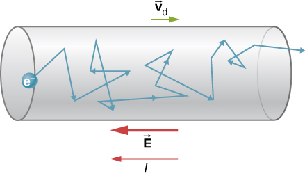
On a microscopic level, current is also related to the drift velocity (vd) of the individual charge carriers. Drift velocity can be thought of as the average velocity of each charge carrier as it moves through a wire. In the image below, we're looking at the path of the electron as it moves through a wire.
Drift velocity is the average velocity of a charged particle, such as an electron, in an electric field. It is the velocity at which the charged particle would move if it were not subjected to any other forces or collisions.
Here are some key points about drift velocity:
- Drift velocity is usually very small compared to the speed of light, and it is typically measured in meters per second.
- Drift velocity is determined by the strength of the electric field and the charge and mass of the charged particle. The stronger the electric field and the lighter the charged particle, the higher the drift velocity.
- Drift velocity is not the same as the speed of the charged particle. The charged particle may be moving at a much higher speed due to other forces and collisions, but its drift velocity is the average velocity it would have if it were not subjected to these other forces.
- Drift velocity is an important concept in electromagnetism and is used to understand and analyze the movement of charged particles in electric fields.
- Drift velocity is related to the conductivity of a material. Materials with high conductivity have a high drift velocity, which means that the charged particles can move through the material more easily. This makes the material a good conductor of electricity.

Image from openstax.org
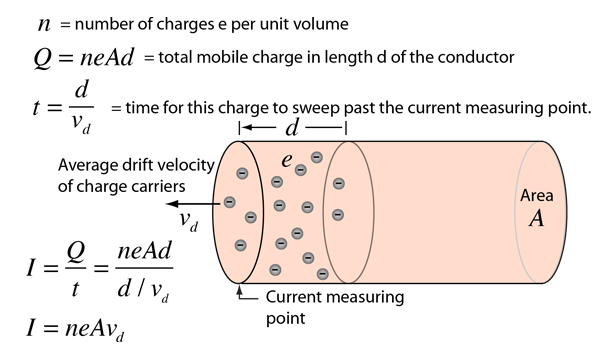
We can imagine that the current in the wire would depend on the total number of charge carriers moving through the wire as well. A larger diameter wire would allow for more carriers. Combining these ideas together we can derive an equation for current.

Image from hyperphysics
Example Problem:
A metal wire has a cross-sectional area of 1 square millimeter and is subjected to an electric field of 1000 volts per meter. The wire is made of a metal with a drift velocity of 1 millimeter per second for electrons. Calculate the electric current flowing through the wire.
Solution:
To solve this question, you would need to use the formula for electric current, which is I = qA vd, where I is the electric current, q is the electric charge of the charged particles (in this case, electrons), A is the cross-sectional area of the wire, and vd is the drift velocity of the charged particles. Using the given values, the electric current flowing through the wire would be:
I = (1.6 x 10^-19 C) * (1 mm^2) * (1 mm/s) = 1.6 x 10^-19 C/s = 1.6 x 10^-15 A
Note that the electric current is very small because the drift velocity of the electrons is very small and the electric charge of an electron is also very small.
Circuit Symbols & Measuring Tools 🛠️
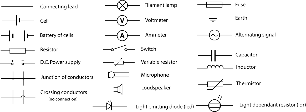
To easily draw circuits, we use a variety of symbols to represent common components. Here are a few common ones, and there are many many more that are not used in AP 2 (although if you become an electrical engineer you'll use them!)

Image from wikimedia.org
There are also two tools listed in the image above: the voltmeter and the ammeter. The voltmeter is designed to accurately measure the potential difference between two points. Because of this, it is built with a very high internal resistance so as not to create a short circuit when it bridges two points in a circuit. A voltmeter is always connected in parallel around the object you are trying to measure.
On the other hand, an ammeter is designed to measure the current flowing through a part of the circuit. Because it's going to be connected in series with the component it's measuring, the internal resistance of the ammeter is designed to be very small. Hooking up an ammeter or voltmeter in the wrong configuration can lead to short circuits or a meter that doesn't function at all. Be careful in your lab experiments, and check first before you connect them.
An ammeter is a device used to measure the electric current flowing in a circuit, while a voltmeter is a device used to measure the electric potential difference, or voltage, across two points in a circuit.
Here are some key points about ammeters and voltmeters:
- Ammeters are used to measure the electric current flowing in a circuit. They are connected in series with the circuit and measure the current flowing through the circuit.
- Voltmeters are used to measure the voltage, or electric potential difference, across two points in a circuit. They are connected in parallel with the circuit and measure the voltage drop across the points being measured.
- Ammeters and voltmeters are important tools in electrical engineering and are used to diagnose and troubleshoot problems in electrical systems.
- Ammeters and voltmeters have different ranges and sensitivity, meaning they are designed to measure different ranges of current and voltage. It is important to use the appropriate meter for the measurement being taken. Ammeters and voltmeters are usually part of a multimeter, which is a device that can measure multiple electrical quantities, including current, voltage, resistance, and continuity.
<< Hide Menu
4.1 Definition and Conservation of Electric Charge
6 min read•june 18, 2024
Krish Gupta
Daniella Garcia-Loos
Krish Gupta
Daniella Garcia-Loos
Definition and Conservation of Electric Charge
Electric Charge is a property of matter that causes it to feel a force in an electromagnetic field. Electric charge must be conserved. The entire topic of current and circuits is based upon the principle of conservation of charge. We learned about charge and its conservation in the last unit. In this unit, we will focus more on current and how it relates to theconservation of charge.
In Unit 3, we studied voltage and defined it as work per unit charge. There are 2 other important quantities used along with voltage to describe the features of a circuit: current and resistance.
A common analogy for how voltage, current, and resistance are related to each other is to think of an electric circuit like water flowing through a hose. Voltage is similar to the water pressure, current is similar to the amount of water that gets through the hose, and resistance is similar to mud or dirt that gets stuck in the hose and starts to clog it.
Conservation of electric charge refers to the principle that the total electric charge in a closed system remains constant over time. This means that electric charge can be transferred or distributed within the system, but the total amount of charge remains the same.
Here are some key points about conservation of electric charge:
- Conservation of electric charge is a fundamental principle in physics and is a consequence of the law of conservation of mass-energy, which states that the total mass and energy of a closed system remains constant.
- Conservation of electric charge is a result of the symmetry of the laws of physics under charge conjugation, which is the transformation that changes all the charges in a system to their opposites (for example, changing all the positive charges to negative charges and vice versa).
- Conservation of electric charge is an important concept in electromagnetism and is used to understand and analyze the behavior of electric charges and electric fields.
- Conservation of electric charge can be used to predict the behavior of electric charges and electric circuits, including the flow of electric current and the operation of batteries and generators.
Image from freeingenergy.com
Current 💨
Current is defined as the rate at which charge flows through a circuit. It's represented by the equation:
where I is the current (measured in Amps or milliAmps), Q is the charge passing a given point, and t is the time for the charge to pass through that point.
** Conventional Current is defined as the direction a positive charge carrier will travel. This may seem strange to us since chemistry tells us that the electrons are the mobile part of the atom. Nevertheless, there are several advantages to choosing a positive direction, since that aligns with our choices in direction when it comes to electric fields and potential differences (see Unit 1). **
On a microscopic level, current is also related to the drift velocity (vd) of the individual charge carriers. Drift velocity can be thought of as the average velocity of each charge carrier as it moves through a wire. In the image below, we're looking at the path of the electron as it moves through a wire.
Drift velocity is the average velocity of a charged particle, such as an electron, in an electric field. It is the velocity at which the charged particle would move if it were not subjected to any other forces or collisions.
Here are some key points about drift velocity:
- Drift velocity is usually very small compared to the speed of light, and it is typically measured in meters per second.
- Drift velocity is determined by the strength of the electric field and the charge and mass of the charged particle. The stronger the electric field and the lighter the charged particle, the higher the drift velocity.
- Drift velocity is not the same as the speed of the charged particle. The charged particle may be moving at a much higher speed due to other forces and collisions, but its drift velocity is the average velocity it would have if it were not subjected to these other forces.
- Drift velocity is an important concept in electromagnetism and is used to understand and analyze the movement of charged particles in electric fields.
- Drift velocity is related to the conductivity of a material. Materials with high conductivity have a high drift velocity, which means that the charged particles can move through the material more easily. This makes the material a good conductor of electricity.

Image from openstax.org
We can imagine that the current in the wire would depend on the total number of charge carriers moving through the wire as well. A larger diameter wire would allow for more carriers. Combining these ideas together we can derive an equation for current.

Image from hyperphysics
Example Problem:
A metal wire has a cross-sectional area of 1 square millimeter and is subjected to an electric field of 1000 volts per meter. The wire is made of a metal with a drift velocity of 1 millimeter per second for electrons. Calculate the electric current flowing through the wire.
Solution:
To solve this question, you would need to use the formula for electric current, which is I = qA vd, where I is the electric current, q is the electric charge of the charged particles (in this case, electrons), A is the cross-sectional area of the wire, and vd is the drift velocity of the charged particles. Using the given values, the electric current flowing through the wire would be:
I = (1.6 x 10^-19 C) * (1 mm^2) * (1 mm/s) = 1.6 x 10^-19 C/s = 1.6 x 10^-15 A
Note that the electric current is very small because the drift velocity of the electrons is very small and the electric charge of an electron is also very small.
Circuit Symbols & Measuring Tools 🛠️
To easily draw circuits, we use a variety of symbols to represent common components. Here are a few common ones, and there are many many more that are not used in AP 2 (although if you become an electrical engineer you'll use them!)

Image from wikimedia.org
There are also two tools listed in the image above: the voltmeter and the ammeter. The voltmeter is designed to accurately measure the potential difference between two points. Because of this, it is built with a very high internal resistance so as not to create a short circuit when it bridges two points in a circuit. A voltmeter is always connected in parallel around the object you are trying to measure.
On the other hand, an ammeter is designed to measure the current flowing through a part of the circuit. Because it's going to be connected in series with the component it's measuring, the internal resistance of the ammeter is designed to be very small. Hooking up an ammeter or voltmeter in the wrong configuration can lead to short circuits or a meter that doesn't function at all. Be careful in your lab experiments, and check first before you connect them.
An ammeter is a device used to measure the electric current flowing in a circuit, while a voltmeter is a device used to measure the electric potential difference, or voltage, across two points in a circuit.
Here are some key points about ammeters and voltmeters:
- Ammeters are used to measure the electric current flowing in a circuit. They are connected in series with the circuit and measure the current flowing through the circuit.
- Voltmeters are used to measure the voltage, or electric potential difference, across two points in a circuit. They are connected in parallel with the circuit and measure the voltage drop across the points being measured.
- Ammeters and voltmeters are important tools in electrical engineering and are used to diagnose and troubleshoot problems in electrical systems.
- Ammeters and voltmeters have different ranges and sensitivity, meaning they are designed to measure different ranges of current and voltage. It is important to use the appropriate meter for the measurement being taken. Ammeters and voltmeters are usually part of a multimeter, which is a device that can measure multiple electrical quantities, including current, voltage, resistance, and continuity.

© 2024 Fiveable Inc. All rights reserved.