Browse By Unit
Krish Gupta
Daniella Garcia-Loos
Krish Gupta
Daniella Garcia-Loos
Resistance and Capacitance
What's a Capacitor?
A capacitor is a device that can be used to store charge, and therefore, electrical potential energy. They are used in a wide range of electrical devices including the flash on your cell phone camera. There are several different ways to construct a capacitor, but we're going to focus on the parallel-plate version.
A capacitor is a device that stores electric charge and energy in an electric field. It consists of two conductors, called plates, separated by an insulating material called the dielectric.
Here are some key points about capacitors:
- Capacitors are used in a variety of electrical and electronic circuits to store and release electric charge and energy. They are used to smooth out voltage fluctuations, filter signals, and store electrical energy.
- Capacitance is a measure of the ability of a capacitor to store electric charge and energy. It is represented by the symbol "C" and is measured in units of farads (F). Capacitance is determined by the size and shape of the capacitor plates and the type and thickness of the dielectric material.
- The electric potential difference, or voltage, across a capacitor is directly proportional to the amount of electric charge stored on the capacitor plates. This relationship is described by the equation Q = C*V, where Q is the electric charge, C is the capacitance, and V is the voltage.
- Capacitors have a characteristic called impedance, which is a measure of the opposition of a circuit element to the flow of electric current.
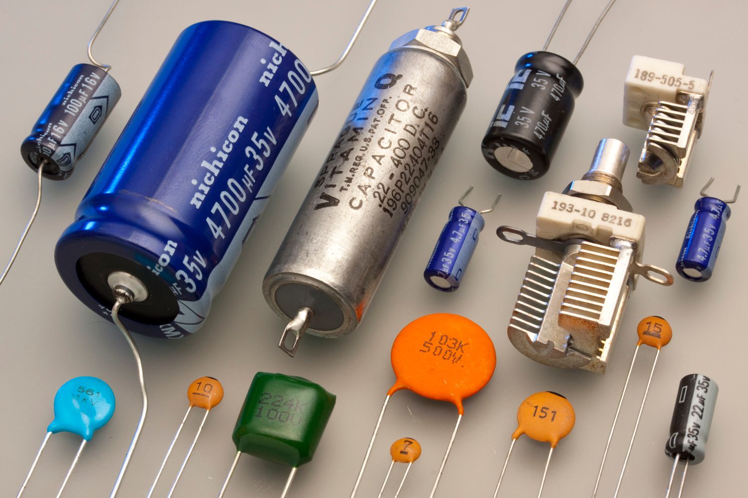
Image from Wikipedia
The parallel plate capacitor is created by taking two conductive plates and separating them by a small distance. A dielectric is often added to increase the amount of charge a capacitor can store. We'll discuss more about dielectrics in the next section.
Theory Time - Parallel Plate Capacitor 🎓
Let's create a simple capacitor using two metal plates and connect them to a battery to charge them up. Recall from Unit 1, that the strength of the electric field is proportional to the amount charge. E=kQ/r^2
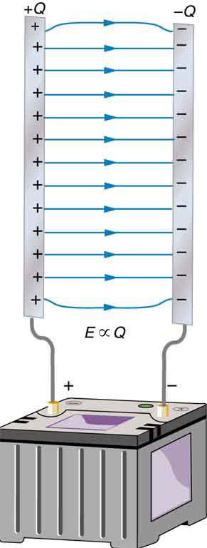
Image from opentextbc.ca
We also know that the potential difference (V) between the plates is related to the electric field through ΔV=Ed. Following this thought process, we can see that V∝Q as well. The more charge that gets stored on each plate, the stronger the field, and the higher the voltage between the plates will be. We'll define a new quantity, capacitance(C), as the constant of proportionality between V and Q such that:
The unit for capacitance is the Farad (F), where 1F =1C/1V
Let's derive what capacitance actually is. This derivation is beyond the course but will give you a deeper understanding of circuits.
We can also define capacitance in terms of the physical dimensions of the capacitor. Recall that σ=Q/A (area charge density) for a sheet of charge, and E=σ/ϵ0 for a conductive plate.
This equation is for a capacitor where the plates are separated by air. We're going to tweak this equation a bit in the dielectric section when we discuss different materials to place between the plates.
From here, we can see that capacitance is directly proportional to the area of the plates (A) and inversely proportional to the distance between them. This should make sense since a larger plate has more room for the charge to occupy and, therefore, more should be able to fit on it.
Energy in a Capacitor 💡
Because the capacitor stores charge, it also stores electric potential energy (UC). The amount of energy stored can be determined through a derivation. However, the derivation requires understanding of integral calculus we will just work with the final product.
Energy in a capacitor is the energy stored in the electric field between the capacitor plates. It is a measure of the potential energy of the electric charges stored on the capacitor plates.
Here are some key points about energy in a capacitor:
- The energy stored in a capacitor is directly proportional to the capacitance of the capacitor and the square of the voltage across the capacitor. This relationship is described by the equation U = 1/2CV^2, where U is the energy, C is the capacitance, and V is the voltage.
- The energy stored in a capacitor is a measure of the potential energy of the electric charges stored on the capacitor plates. The electric charges are attracted to the opposite charges on the other plate and are held in place by the electric field between the plates.
- The energy stored in a capacitor can be converted into other forms of energy, such as kinetic energy (the energy of motion), when the capacitor is discharged. The total energy of a closed system, including the energy stored in a capacitor, is conserved.
Take a few minutes and check out this Phet Simulation where you can alter the physical properties of a parallel plate capacitor and see the effect on voltage, field strength, and energy stored.
Practice Questions 👍
- A 20 µF parallel-plate capacitor is fully charged to 20 V. The energy stored in the capacitor is most nearly __________.
Answer:
- A capacitor with circular parallel plates of radius R that are separated by a distance d has a capacitance of C. What would the capacitance (in terms of C ) be if the plates had radius 2R and were separated by a distance d/2 ?
Answer:
The capacitance depends on the area of the plate, which for a circular plate is 2πr^2
What Are Dielectrics?
Dielectrics are insulating materials that are often used in capacitors to increase their capacitance. They help solve the problem of how to get more charge into a capacitor without having the voltage decrease. C=Aϵo/d. Modifying the equation to include a dielectric involves adding a new term κ, which is the dielectric constant. In general, the easier a material is to polarize, the higher it's dielectric constant is. Values for common dielectrics are shown below:
Copy of Common Dielectrics
| Material | Dielectric Constant |
| Vacuum | 1 |
| Air | 1.00059 |
| Bakelite | 4.9 |
| Fused Quartz | 3.78 |
| Neoprene Rubber | 6.7 |
| Nylon | 3.4 |
| Paper | 3.7 |
| Polystyrene | 2.56 |
| Pyrex Glass | 5.6 |
| Silicon Oil | 2.5 |
| Strontium Titanate | 233 |
| Teflon | 2.1 |
| Water | 80 |
Data obtained from lumenlearning.com
Why Does Adding a Dielectric Increase the Capacitance? 😕
Great question! It's because a dielectric becomes polarized easily. In fact, the easier the dielectric becomes polarized, the greater its κ becomes. Let's look at an image to understand why the polarization helps increase the capacitance.
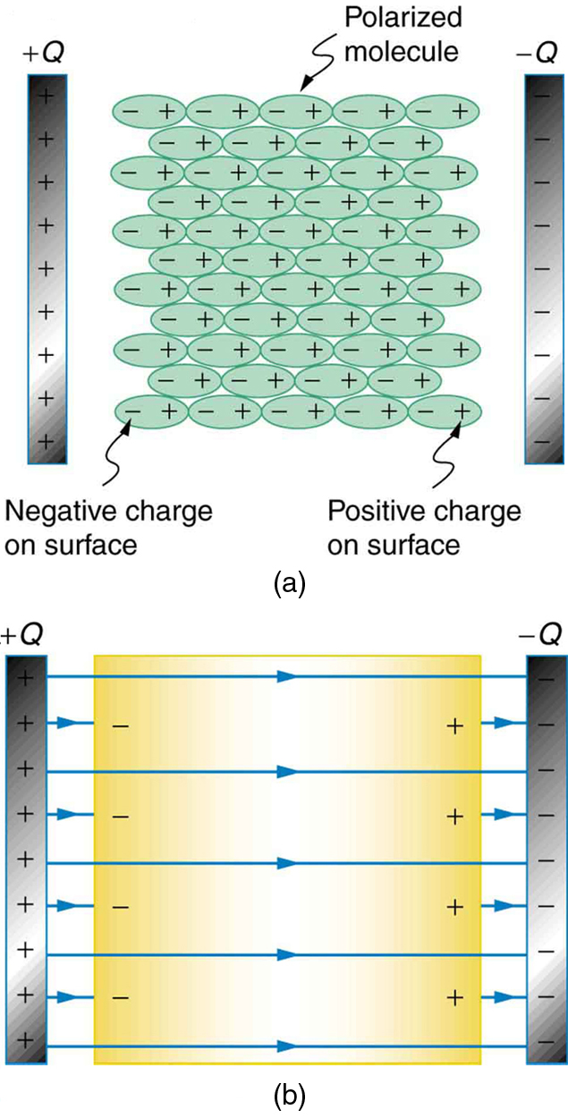
In image (a), we can see that the molecules of the dielectric become polarized and align opposing the charge on the plates. This produces a layer of opposite charge on the surface of the dielectric that attracts more charge onto the plate, because of Coulomb's Law, increasing its capacitance.
Another way to understand how a dielectric increases capacitance is to look at how it changes the electric field inside the capacitor. Image (b) shows the electric field lines with a dielectric in place. Since some of the field lines end on charges in the dielectric (because the polarity of the dielectric is opposite that of the plates), the overall field between the plates is weaker than if there were a vacuum between the plates, even though the same charge is on the plates.
The voltage between the plates is V=Ed, so it is also reduced by the dielectric. This means there is a smaller V for the same charge Q and since C = Q/V, the capacitance is greater.
** After looking back at 20+ years of FRQs, if you see an FRQ on circuits, there's a really good chance it will have a capacitor in it. You've been warned 🙂**
Capacitors in Series & Parallel
Capacitors have their own special equations for determining equivalent resistance in series or parallel, just like resistors.

Image from lumenlearning.com
For a parallel circuit, individual capacitors act as one large capacitor storing a large charge (Qtotal = Q1 + Q2 +Q3) resulting in a total capacitance that is simply the sum of the individual values.
A series circuit is a bit trickier since the charge is split up along each of the capacitors, but we can derive an expression for this by using the KVL (sum of voltage drops needs to be equal to the battery voltage)
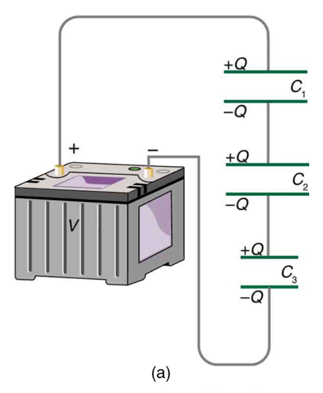
Image from lumenlearning.com
Steady State Behavior 🎯
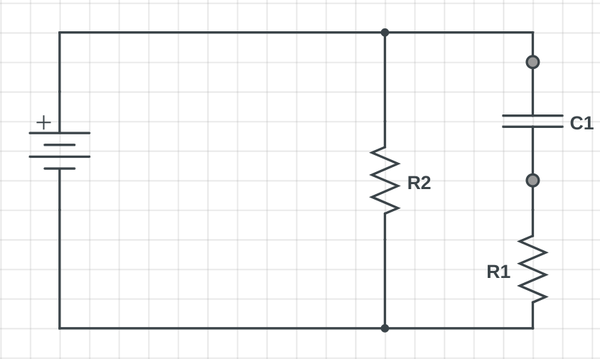
In a DC circuit, an initially uncharged capacitor will begin storing charge on its plates, increasing its potential difference until the voltage of the capacitor is equal to the voltage of the battery or other supply source. At this point, there is no current passing through the capacitor and it acts as an open switch or a break in the wire.
For example, in the circuit below, the current initially flows through both branches, but as the voltage of C1 approaches the battery voltage, less and less current passes through R1. When steady state is reached, the circuit will appear to be a series circuit with only R2 in it.
RC Circuits 🏍️
The RC circuit is a very common type of capacitor where a resistor and capacitor are connected in series with each other. A switch is used to allow the capacitor to charge (position a) or discharge (position b).
An RC circuit is a type of electrical circuit that contains a resistor and a capacitor connected in series or parallel. RC circuits are used to filter signals, smooth out voltage fluctuations, and discharge stored energy.
Here are some key points about RC circuits:
- RC circuits are named after the two components they contain: a resistor (R) and a capacitor (C). The resistor and capacitor are connected in series or parallel to form the circuit.
- RC circuits are used in a variety of electrical and electronic applications to filter signals, smooth out voltage fluctuations, and discharge stored energy. They are used in power supplies, audio circuits, and oscillators, among other applications.
- The behavior of an RC circuit depends on the values of the resistor and capacitor and the frequency of the applied voltage. At high frequencies, the capacitor acts as a short circuit and allows most of the current to pass through, while at low frequencies, the capacitor acts as an open circuit and blocks most of the current. This frequency-dependent behavior is called impedance.
- RC circuits can be used to create resonant circuits, which are circuits that amplify and oscillate at a particular frequency. Resonant circuits are used in radio transmitters and receivers, oscillators, and other electronic devices.
- RC circuits can be analyzed using Kirchhoff's laws, Ohm's law, and the equations of capacitor and resistor behavior. These tools are used to predict the voltage and current in the circuit and to design and troubleshoot RC circuits.
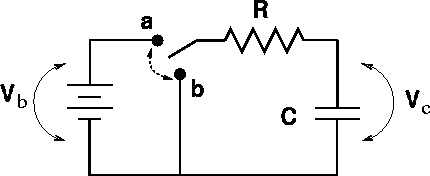
Image from web.pa.msu.eduT
The cool thing about RC circuits is that the charging and discharging time can be tweaked by changing the values of C and R.
Knowing the exact equations or graphs of RC Circuit equations in not on the exam but will help enhance your understanding. Graphing these functions shows us the changes in V and I as the capacitor charges. Notice how when the steady-state is reached, the current in the capacitor is basically zero.
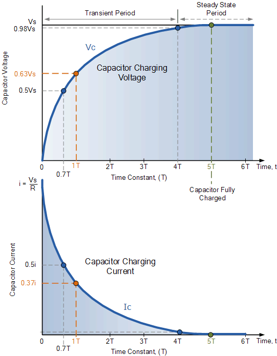
Image from electronics-tutorials.ws
Now we can make the same sort of graphs as we did for the charging segment.
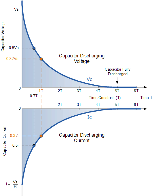
Image from electronics-tutorials.ws/
<< Hide Menu
Krish Gupta
Daniella Garcia-Loos
Krish Gupta
Daniella Garcia-Loos
Resistance and Capacitance
What's a Capacitor?
A capacitor is a device that can be used to store charge, and therefore, electrical potential energy. They are used in a wide range of electrical devices including the flash on your cell phone camera. There are several different ways to construct a capacitor, but we're going to focus on the parallel-plate version.
A capacitor is a device that stores electric charge and energy in an electric field. It consists of two conductors, called plates, separated by an insulating material called the dielectric.
Here are some key points about capacitors:
- Capacitors are used in a variety of electrical and electronic circuits to store and release electric charge and energy. They are used to smooth out voltage fluctuations, filter signals, and store electrical energy.
- Capacitance is a measure of the ability of a capacitor to store electric charge and energy. It is represented by the symbol "C" and is measured in units of farads (F). Capacitance is determined by the size and shape of the capacitor plates and the type and thickness of the dielectric material.
- The electric potential difference, or voltage, across a capacitor is directly proportional to the amount of electric charge stored on the capacitor plates. This relationship is described by the equation Q = C*V, where Q is the electric charge, C is the capacitance, and V is the voltage.
- Capacitors have a characteristic called impedance, which is a measure of the opposition of a circuit element to the flow of electric current.

Image from Wikipedia
The parallel plate capacitor is created by taking two conductive plates and separating them by a small distance. A dielectric is often added to increase the amount of charge a capacitor can store. We'll discuss more about dielectrics in the next section.
Theory Time - Parallel Plate Capacitor 🎓
Let's create a simple capacitor using two metal plates and connect them to a battery to charge them up. Recall from Unit 1, that the strength of the electric field is proportional to the amount charge. E=kQ/r^2

Image from opentextbc.ca
We also know that the potential difference (V) between the plates is related to the electric field through ΔV=Ed. Following this thought process, we can see that V∝Q as well. The more charge that gets stored on each plate, the stronger the field, and the higher the voltage between the plates will be. We'll define a new quantity, capacitance(C), as the constant of proportionality between V and Q such that:
The unit for capacitance is the Farad (F), where 1F =1C/1V
Let's derive what capacitance actually is. This derivation is beyond the course but will give you a deeper understanding of circuits.
We can also define capacitance in terms of the physical dimensions of the capacitor. Recall that σ=Q/A (area charge density) for a sheet of charge, and E=σ/ϵ0 for a conductive plate.
This equation is for a capacitor where the plates are separated by air. We're going to tweak this equation a bit in the dielectric section when we discuss different materials to place between the plates.
From here, we can see that capacitance is directly proportional to the area of the plates (A) and inversely proportional to the distance between them. This should make sense since a larger plate has more room for the charge to occupy and, therefore, more should be able to fit on it.
Energy in a Capacitor 💡
Because the capacitor stores charge, it also stores electric potential energy (UC). The amount of energy stored can be determined through a derivation. However, the derivation requires understanding of integral calculus we will just work with the final product.
Energy in a capacitor is the energy stored in the electric field between the capacitor plates. It is a measure of the potential energy of the electric charges stored on the capacitor plates.
Here are some key points about energy in a capacitor:
- The energy stored in a capacitor is directly proportional to the capacitance of the capacitor and the square of the voltage across the capacitor. This relationship is described by the equation U = 1/2CV^2, where U is the energy, C is the capacitance, and V is the voltage.
- The energy stored in a capacitor is a measure of the potential energy of the electric charges stored on the capacitor plates. The electric charges are attracted to the opposite charges on the other plate and are held in place by the electric field between the plates.
- The energy stored in a capacitor can be converted into other forms of energy, such as kinetic energy (the energy of motion), when the capacitor is discharged. The total energy of a closed system, including the energy stored in a capacitor, is conserved.
Take a few minutes and check out this Phet Simulation where you can alter the physical properties of a parallel plate capacitor and see the effect on voltage, field strength, and energy stored.
Practice Questions 👍
- A 20 µF parallel-plate capacitor is fully charged to 20 V. The energy stored in the capacitor is most nearly __________.
Answer:
- A capacitor with circular parallel plates of radius R that are separated by a distance d has a capacitance of C. What would the capacitance (in terms of C ) be if the plates had radius 2R and were separated by a distance d/2 ?
Answer:
The capacitance depends on the area of the plate, which for a circular plate is 2πr^2
What Are Dielectrics?
Dielectrics are insulating materials that are often used in capacitors to increase their capacitance. They help solve the problem of how to get more charge into a capacitor without having the voltage decrease. C=Aϵo/d. Modifying the equation to include a dielectric involves adding a new term κ, which is the dielectric constant. In general, the easier a material is to polarize, the higher it's dielectric constant is. Values for common dielectrics are shown below:
Copy of Common Dielectrics
| Material | Dielectric Constant |
| Vacuum | 1 |
| Air | 1.00059 |
| Bakelite | 4.9 |
| Fused Quartz | 3.78 |
| Neoprene Rubber | 6.7 |
| Nylon | 3.4 |
| Paper | 3.7 |
| Polystyrene | 2.56 |
| Pyrex Glass | 5.6 |
| Silicon Oil | 2.5 |
| Strontium Titanate | 233 |
| Teflon | 2.1 |
| Water | 80 |
Data obtained from lumenlearning.com
Why Does Adding a Dielectric Increase the Capacitance? 😕
Great question! It's because a dielectric becomes polarized easily. In fact, the easier the dielectric becomes polarized, the greater its κ becomes. Let's look at an image to understand why the polarization helps increase the capacitance.

In image (a), we can see that the molecules of the dielectric become polarized and align opposing the charge on the plates. This produces a layer of opposite charge on the surface of the dielectric that attracts more charge onto the plate, because of Coulomb's Law, increasing its capacitance.
Another way to understand how a dielectric increases capacitance is to look at how it changes the electric field inside the capacitor. Image (b) shows the electric field lines with a dielectric in place. Since some of the field lines end on charges in the dielectric (because the polarity of the dielectric is opposite that of the plates), the overall field between the plates is weaker than if there were a vacuum between the plates, even though the same charge is on the plates.
The voltage between the plates is V=Ed, so it is also reduced by the dielectric. This means there is a smaller V for the same charge Q and since C = Q/V, the capacitance is greater.
** After looking back at 20+ years of FRQs, if you see an FRQ on circuits, there's a really good chance it will have a capacitor in it. You've been warned 🙂**
Capacitors in Series & Parallel
Capacitors have their own special equations for determining equivalent resistance in series or parallel, just like resistors.

Image from lumenlearning.com
For a parallel circuit, individual capacitors act as one large capacitor storing a large charge (Qtotal = Q1 + Q2 +Q3) resulting in a total capacitance that is simply the sum of the individual values.
A series circuit is a bit trickier since the charge is split up along each of the capacitors, but we can derive an expression for this by using the KVL (sum of voltage drops needs to be equal to the battery voltage)

Image from lumenlearning.com
Steady State Behavior 🎯
In a DC circuit, an initially uncharged capacitor will begin storing charge on its plates, increasing its potential difference until the voltage of the capacitor is equal to the voltage of the battery or other supply source. At this point, there is no current passing through the capacitor and it acts as an open switch or a break in the wire.
For example, in the circuit below, the current initially flows through both branches, but as the voltage of C1 approaches the battery voltage, less and less current passes through R1. When steady state is reached, the circuit will appear to be a series circuit with only R2 in it.

RC Circuits 🏍️
The RC circuit is a very common type of capacitor where a resistor and capacitor are connected in series with each other. A switch is used to allow the capacitor to charge (position a) or discharge (position b).
An RC circuit is a type of electrical circuit that contains a resistor and a capacitor connected in series or parallel. RC circuits are used to filter signals, smooth out voltage fluctuations, and discharge stored energy.
Here are some key points about RC circuits:
- RC circuits are named after the two components they contain: a resistor (R) and a capacitor (C). The resistor and capacitor are connected in series or parallel to form the circuit.
- RC circuits are used in a variety of electrical and electronic applications to filter signals, smooth out voltage fluctuations, and discharge stored energy. They are used in power supplies, audio circuits, and oscillators, among other applications.
- The behavior of an RC circuit depends on the values of the resistor and capacitor and the frequency of the applied voltage. At high frequencies, the capacitor acts as a short circuit and allows most of the current to pass through, while at low frequencies, the capacitor acts as an open circuit and blocks most of the current. This frequency-dependent behavior is called impedance.
- RC circuits can be used to create resonant circuits, which are circuits that amplify and oscillate at a particular frequency. Resonant circuits are used in radio transmitters and receivers, oscillators, and other electronic devices.
- RC circuits can be analyzed using Kirchhoff's laws, Ohm's law, and the equations of capacitor and resistor behavior. These tools are used to predict the voltage and current in the circuit and to design and troubleshoot RC circuits.

Image from web.pa.msu.eduT
The cool thing about RC circuits is that the charging and discharging time can be tweaked by changing the values of C and R.
Knowing the exact equations or graphs of RC Circuit equations in not on the exam but will help enhance your understanding. Graphing these functions shows us the changes in V and I as the capacitor charges. Notice how when the steady-state is reached, the current in the capacitor is basically zero.

Image from electronics-tutorials.ws
Now we can make the same sort of graphs as we did for the charging segment.

Image from electronics-tutorials.ws/

© 2024 Fiveable Inc. All rights reserved.